|
25mm ARMAMENT POSITIONING (Final Sortie)
This "Operation Zuiho" page is a collection of data to assist me in building this ship in a wooden and plastic version at 1/100 scale. As of April 2016 I have begun preparing for
construction to begin. One of the most difficult (dare I say impossible) parts of this process has been defining what the Zuiho's 25mm AA mount layout was. As far as all my
investigations are concerned, no one really knows what the disposition was of her 25mm mounts; with the single 25mm mounts being considerably harder to define. Only two or three
photos of her exist in this final configuration and all are taken from attacking aircraft with limited definition and detail. What is known is that the Japanese put as many single
mounts as possible onto the Zuiho for what would ultimately be her final battle. As Ed Low quipped, "25mm guns are cheap and aircraft carriers are expensive."
So, I have to try to place the 25mm guns as history, other images of IJN carriers of 1944 and 1945 and common sense allow. I also am working with the accepted 68 x 25mm gun barrels.
The Twin 25mm Mounts (8 barrels):
The twin mounts are easiest. The general consensus is that they had 4 mounts, equaling 8 x 25mm barrels. These were located ahead of the bridge, under the flight deck, two mounts per side.
The Triple 25mm Mounts (36 barrels):
Nearly all post-WWII drawings of the Zuiho had 10 triple mounts as of October of 1944. However, we know that before the flight deck was extended forward, the Zuiho had 2 x triple
mounts immediately ahead of the flight deck, on the bow. Once the flight deck was lengthened, were these two triples moved onto platforms off the second set of flight deck support
posts? Or were these 2 x triple 25mm mounts left in place and an ADDITIONAL 2 x triple 25mm added to platforms off the second set of flight deck supports? That is the question
that begs an answer, but there is zero evidence to support either claim with regards to the fate of those pesky foremost 2 x triple 25mm mounts. I have therefore decided to include
the original 2 x triple mounts in the October 1944 version of the Zuiho. Their traverse and elevation would have been more limited than most the other 25mm on this ship, but they would
have provided excellent low level firepower off the bow of the ship. So, this means there were 12 x triple 25mm mounts, equaling 36 x 25mm barrels.
The Single 25mm Mounts (24 barrels):
The single mounts are by far the most difficult to place on the Zuiho. To add to the difficulty is the addition of "sleighs". These were "portable" single 25mm guns that could be bolted
to the flight deck. They could be moved or stowed when flight operations were underway. To me, the sleigh is the ultimate in evidence as to the plight of the Japanese carriers in the last
few months of the war. Each sleigh weighed at least 1,000lbs. To man-handle these onto the deck between take off and landings would have been time intensive and a real headache for the crew.
They would also have had to drag the ammunition boxes out and back AND picked up all the empty shell casings before planes could operate on the deck. To incorporate the sleighs on their
carriers provides a fresh perspective on Japanese desperation. The Japanese could not fill the hangars with planes and pilots by the end, so they had to resort to piling AA weapons on
the ship in any way they could. I digress.
The reason the sleighs make this exercise difficult is no one knows how many were used (5 is the consensus), but why would they stop at only 5? Also, was the number of sleighs put aboard
included in the final 68 barrel count or not? I had to make some assumptions: there were 5 sleighs and they were included in the 68 barrel count. Is this historically accurate? No one knows...
Okay, with 5 sleighs we now need to account for the 19 other single mounts. For the uninitiated: the single mount was very easy to install. The base of the pedestal had a ring mount with 8 bolts.
All the crew had to do was find a spot that could support a little under 2,000lbs of weight (gun, ammo, gun crew members milling about) and bolt the gun to the deck. I am over simplifying
the process a tad, but you get the picture. No two drawings of the Zuiho I have seen place the single 25mm mounts in the same place. What to do? I really just need to use my judgement and photos
of other carriers to place the single 25mm pedestal mounts.
I will admit that the lack of historical evidence is both frustrating and liberating at the same time. I get to use my own judgement on the layout of these guns and no one can unequivocally
say I am wrong... Unless new data surfaces that refutes what I decided to do. I can be confident that I built the model with the information I had at hand.
Here is the final 25mm layout I have decided upon:
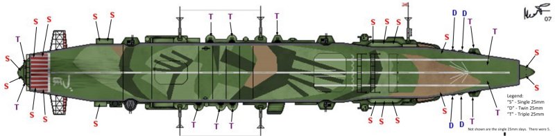
The positioning and firing arcs of some of the "unknown" 25mm mounts are reviewed here:

The 2 x triple mounts that were "most likely" under the flight deck at the bow prompted discussion at j-aircraft.com. This picture shows the plan position of those mounts and what their
fire arcs would have been horizontally. With firing inhibitors placed to stop the guns from firing at the two flight deck support posts, the lateral traverse of these guns is almost 180
degrees. Acceptable firing arcs!

The side by side single 25mm pedestals would have probably sported a half moon radial catwalk, to allow the gunners to pivot the gun and not have to worry about the sloping deck.

These two guns would have been just forward of the hawseholes (where the anchor chain feeds from the deck, into the sea).
THE ODESSEY OF THE BOW 25MM MOUNTS (Final Sortie)
Over the course of several weeks I have been studying the bow section and the arrangement of 25mm mounts. The common understanding is that the Zuiho had 2 triple mounts and 4 twin
mounts on the bow of the ship. This understanding has been further augmented recently with a further two triples under the flight deck, just ahead of the superstructure. Then, as
mentioned in the previous section, 2 more singles were probably located on the extreme bow. I turn the reader's attention to the four twin mounts and propose to you that there were
only two twin mounts. Indeed, the assumed positioning of these four twins was that each pair of twins was conjoined twins (positioned very close together) and on round platforms that
extended over each beam. There is absolutely no photographic evident to support this.
Let me illustrate with images:

The above image shows what the general consensus was of the layout of the bow 25mm guns. It is wrong.

We know that there were two triple (or maybe twin) guns under the flight deck fore. We will leave the single mounts out of the image presently to keep the image clearer. Note the
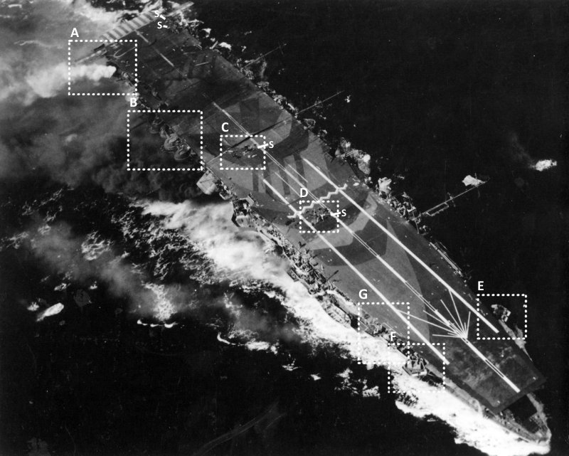
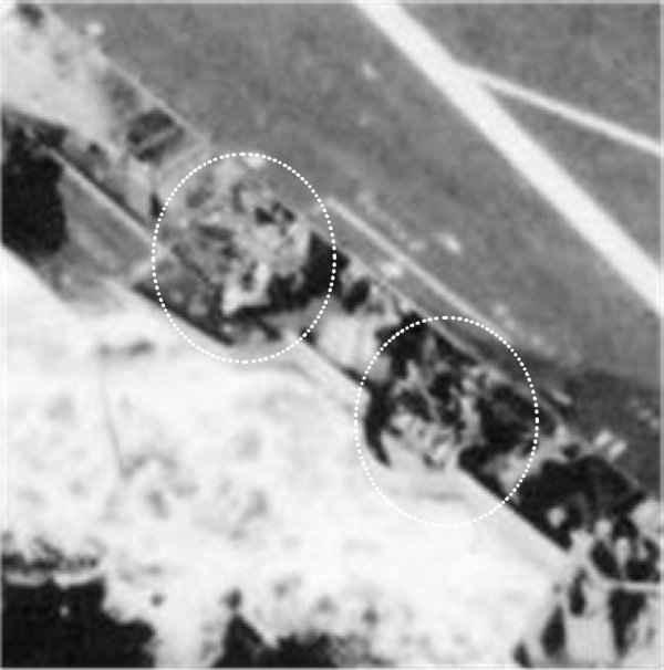
closeness of the twin mounts. Now look at the following image of a photo of the ship in action on her last sortie, where the bow section is blown up for the sake of ease of viewing:

Here we can clearly see one round platform extending out for a twin mount and we can see the raised triple mount bandstand, but where is the second round platform that is supposed to
be sandwiched together with the one that is visible?

I added some coloured red lines to accentuate my idea. First I thought that perhaps the raised triple's bandstand was concealing the forward twin and I added the second red circle
where the other twin might have been. Acceptable? Yes.
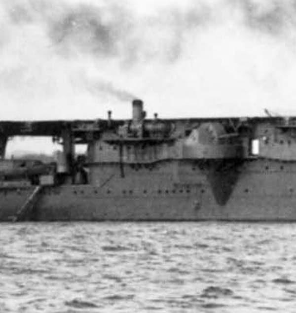
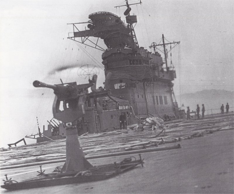
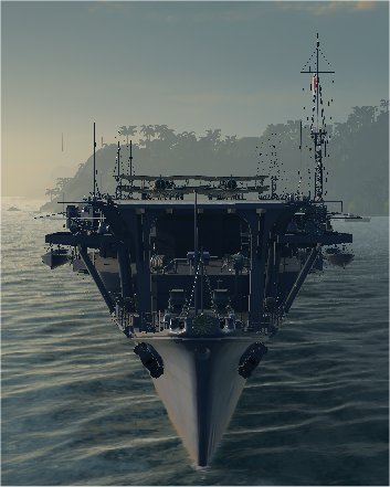
Then I looked at another image provided to me where the ship is showing more of a broadside:

This image is actually pretty cool as the foremost triple mount that is under the flight deck is clearly shown, but I digress. Once again, the foremost twin platform is nowhere to be seen.
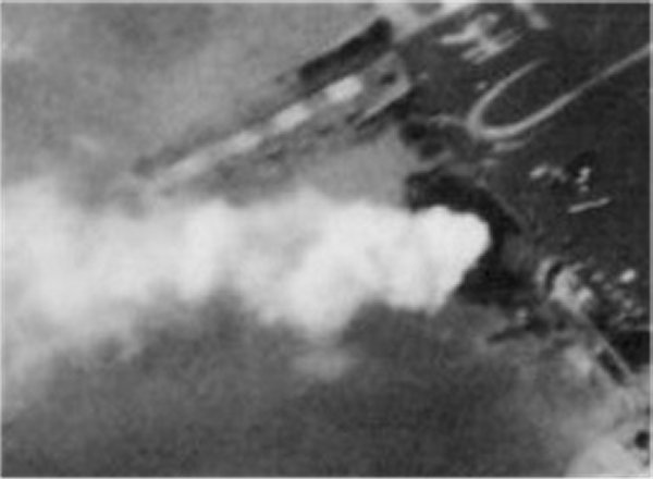
Then I decided to dig up "that" photo of the forward 25 mm guns taken aft of them. I did a little projection and here is what I found out:
Image A

There are three mounts (or barrels of those mounts) visible, if not four! Someone else has drawn circles on the barrels to depict how many there may have been of each. The general
mistake that was previously made was in assuming that this image was actually of the stern of the Zuiho. It has since been found to be the bow. Here is my investigation:
Image B

This image and my markings show the approximate position of the photographer. In "Image A" there is an aerial in the foreground and in "Image B" we can see where that aerial was. I
have then transposed the photographer's position to the starboard side with the solid green arrow. With that done we can now compare this bow shot with the starboard wide shot.
Image C

This image should be used to cross reference when I speak of the different mount A, B, C, D, X
Image D

Okay, I have labeled the mounts from aft to fore as Mount's A thru D in both images above. Let's look at the only real question mark here: Mount B (supposed to be a twin, but looks like a
single). It could be a twin, possibly and the angle of the one barrel is completely hiding the second barrel, but that means mount B is very close to mount A. Look at how close in size the
barrels of mount A and mount B are. We should see its platform extending out over the beam as it is depicted in the plan drawing, but it is not there. Another argument for Mount B being a
single is that single mounts were taller than twin and triple mounts because the gunner needed to stand behind it. The pivot point of a single mount was 1.18M tall and the pivot point of a
twin/triple was .825M. Image D shows that, from the angle the photographer took the picture, the photo's features descend as they move away from the camera. That means, if mount A and B
were both twins, mount B would be lower than mount A. Mount B is not lower and its pivot point could be drawn as being the same or slightly higher than mount A's. Lastly, mounts A, C and
D are all pointed at high angles, why isn't mount B's gun? If it were resting on someone's shoulders, as a single would, the barrel's angle would be more horizontal as depicted in this image.

I took the bow 25mm image and superimposed the plan view of a 25mm cannon and resized and angled them to match the angles on the image. I think this is quite conclusive. The single mount's
(green overlay) pivot point is slightly higher than the twin's (red overlay) pivot point, as a single mount was taller in reality than a twin mount. If both mounts A and B were twins, following the perspective of
the photo, then Mount B's pivot point should be lower than that of Mount A's.
Finally, some people think that the other twin mount could have been aft of mount A and therefore not in this picture. If you look at the plan view image, there is a flight deck support post
there, the bridge superstructure flairs out there and there is a lifeboat as well. That location is a major foot traffic area from the bow and bridge to the rear of the ship. It would not
have made for an optimal location for a twin mount.

July 1944
July 1944 saw extensive increases to the Zuihos AA suite and the lengthening of her flight deck forward. This included the addition of the bandstands on her second support post that
were not mentioned in the July 1944 blueprint (7_1944_BP). I can see no evidence that all four twins were ever installed immediately in front of her bridge, although they were
"planned" to go there. I think it is only logical to assume the gun placement and rearrangement probably matched what I suggest. I am not stating unequivocally
that this is historically accurate, but that I personally think this is accurate and I will be incorporating this into my 1/100 build of her.
I really imagine the July 1944 blueprints being created before July 1944, using the original deck size, to plan new mounts placements. When the time came, "someone" decided to extend the flight
deck forward and changes needed to be made to the layout. With Mount C being added, the placement of the twins needed to be rethought. The original plan made sense regarding the placement of the
twins, if the triples stayed where they were at Mount D. But the triples from Mount D were moved onto the new bandstands at Mount C. Now the twins needed to be redistributed to give them better
locations. I know all this is conjecture, but as I try to keep my mind open to other possibilities, this one still seems like the most plausible explanation of the sequence of events.
Before I started this portion of investigation, I thought the flight deck was extended in September of 1943 (I cannot remember where I got that idea from) and I had never seen the July 1944 blueprints.
If the flight deck had been extended in 1943, then the July 1944 blueprints would have indicated the extension and, more importantly, my hypothesis would have been on much thinner ice. But seeing as
these blueprints were for a planned July 1944 AA augmentation project and then the flight deck was lengthened, the plans would have had to have changed once the longer flight deck was in place.
We do not have the changed plans (unless someone unearths them after I have recorded this investigation!). Balancing this knowledge with the fact that the photos "seem" to support my theory, I have
come to the following educated, but not proven, conclusions:
In July of 1944 the following changes occurred:
1. Fight deck extended forward (fact).
2. Mount A was installed (fact).
3. Mount C was created (fact).
4. The triple guns of Mount D were moved to Mount C (probable, but no evidence).
5. Mount B was removed (or was never installed) as planned with a twin mount in the July 1944 BP (probable based on photos).
6. The twin guns planned for Mount B were instead used on Mount D (probable, but no evidence).
7. A single gun was installed where Mount B was planned to go; creating a new Mount B without the platform jutting out (probable based on photos available).
8. Mount X had a single gun and remained unchanged (probable based on 1944 BP).
For clarification of the above information here is the final theoretical 25mm configuration for Oct 1944:
Mount A = Twin 25mm
Mount B = Single 25mm
Mount C = Triple 25mm
Mount D = Either twin or triple 25mm, but I am now leaning towards twin 25mm (see below)
Mount X = Single 25mm
Mount Z = Single 25mm (If this position ever existed it cannot be confirmed with any documentation or images)
I am leaning towards not including Mount Z as I can't find anything to confirms it's existence.
I removed the bow mount Z and I also moved mount A and B forward a bit to mirror the photos I have been referencing.
Photos and plans to support my argument:

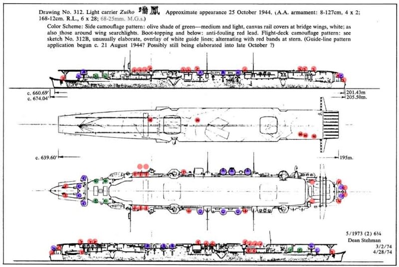
This is a portion of the July 1944 BP as provided to me by D.Kaplan. It shows the following: the flight deck was still short, the proposed positioning of the 4 twins (in pink) and the
already placed two triples (Mount D) and two singles (Mount X)

I further marked up this image by connecting the three visible railing heads with a dotted red line. This shows the perspective angle. If mount B were a twin it's pivot point,
marked in teal, would be much lower than mount A's pivot point, marked in yellow.
I guess at this point I challenge anyone to prove this layout wrong. I have reached the point that I can honestly say that no one has given me any proof (through photos or official blueprints or
first person transcripts) that there even were two sets of twins at either combinations of Mounts A and B or at Mounts A and X! What I have received is one July 1944 blueprint that the
Oct 1944 photos prove incorrect (or at least that further changes were done to the twin placement after the July 1944 BP was created).

DID YOU KNOW?
This section provides you with important information pertaining to the Zuiho that doesn't really fit in any other section:
Zuiho had a two-level hangar
Both elevators were octagonal and on the centerline. The aft elevator being smaller than the forward elevator
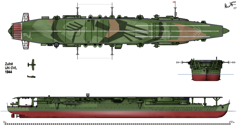
She had a single downward facing funnel to starboard
Originally designed as a fast oiler with the name "Takasaki"
Oil bunkers were designed to carry 2,600 tonnes of fuel oil
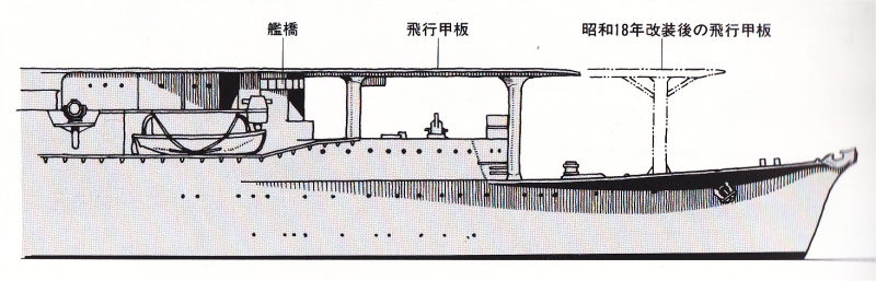
She was a flush deck design with no island bridge. The bridge was under the flight deck near the bow which was a design feature
Japan integrated into all their light and escort carriers. The only country to do so as standard design practice.
The propulsion machinery was that of the Kagero class destroyers
An auxiliary exhaust stack (also know as a donkey stack) was located aft starboard
The "donkey stack" was used to provide exhaust for the heating system boilers and possibly the steam-driven electric generators
In September 1943 the Zuiho's flight deck was lengthened forward from 180 meters LOA to 192.6 meters
In 1944 the ship received 120mm AA rockets in 6 sets of 28 (3 sets grouped and located aft starboard
(aft of the aft covered twin 12.7 mount) and 3 sets grouped and located portside aft/amidships (fore of the aft twin 12.7mm mount))
The ship never operated dive bombers. They did use the Zero fighter as a fighter/bomber.
To augment the Zuiho's anti-air suite of 25mm guns in 1944, several single 25mm mounts were added to any sponsons where space provided. The
Zuiho also had at least 5 single 25mm guns on "sleighs". These sleighs were portable platforms that could be screwed driectly to the flight deck.
The sleighs would have needed to have been removed whenever the ship was landing, launching or spotting aircraft.
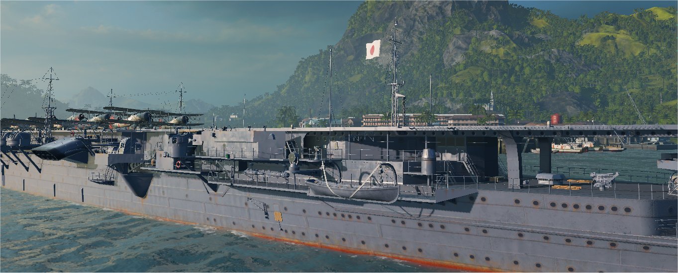
The following is an interesting feature of some Japanese aircraft carriers - especially with the medium and light carriers due to limited flight deck space (across the beam)
The 12.7mm twin guns were the heaviest caliber of weapon on these carriers and they were almost exclusively used to shoot at attacking aircraft. They were dual purpose guns, but
the battles of the time saw them focused on a single use - disabling or destroying aircraft. Due to the width (beam) of the hull and flight deck, and the need to make the most of
these 12.7mm guns, the Japanese designed the flight deck to have an indent in the flight deck behind each of the 12.7mm gun mounts. This allowed the mounts to swivel, at extreme
barrel elevation and fire at high flying aircraft over the carrier and even on the opposite beam. The addition of these indents meant that, theoretically, if a plane was flying
in a specific quadrant of the airspace surrounding the carrier ALL 12.7mm guns could be brought to bear and fired. These indents allowed for that level of flexibility. However,
the drawback to these indents was that they were quite large and probably extended 6 to 8 feet inboard. This literally created holes along the edge of the flight deck that could prove
hazardous to landing aircraft. These indents (especially the ones aft of amidships) would probably also have affected spotting of the aircraft on deck during take-off placement. With
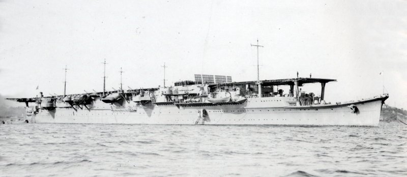
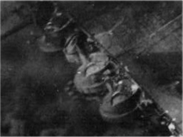
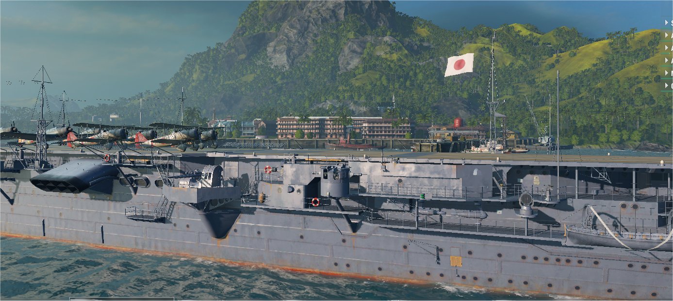
this in mind the Japanese created a unique system. The gun mount indents were actually created by lifting the flight deck section up and out of the way! As can be seen in the
photos below, there are mirror shaped objects adjacent to each indent. It is clear that these would have been retracted and replaced on a hinge system. Whether there was an electric
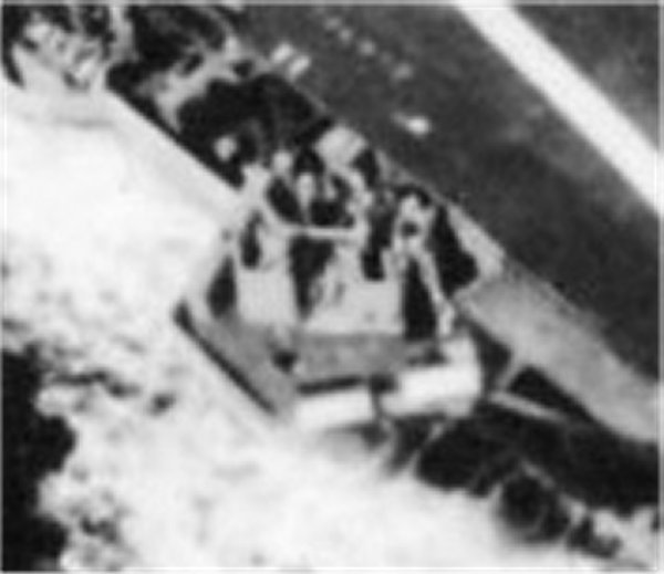
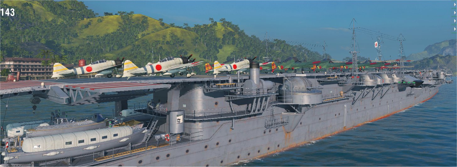
or hydraulic motor involved, hand cranked gears or the piece was lifted via the arms, backs and legs of sailors is not known. In the final image we can see a picture of the same
gun mount on the same class of ship while the ship is in harbor. The flight deck edge is uninterrupted by an indent. An ingenious solution put forward by the Japanese.
| The demi-hexagonal indent is clear as is the mirrored flight deck piece laying upside down beside it |
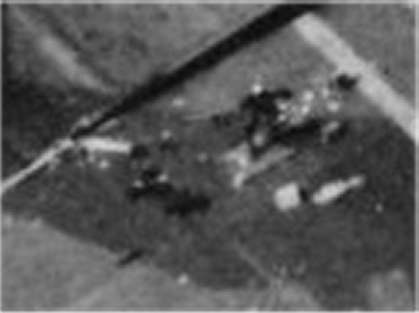
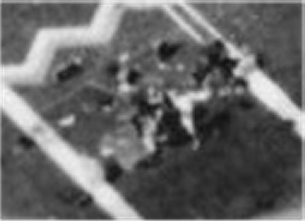
The coloured lines better illustrate the retracted piece of the flight deck and the "flip of the deck" required to close the indent |
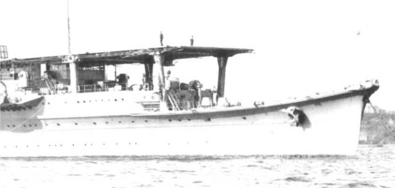
The Shoho, in harbor, with no interruption in her flight deck behind the 12.7mm mount |
 |
 |
 |
|